3

I want to do something very similar to NAT VLans with same IP sub-nets but it is dissimilar enough that I don't know how to apply it to my application.

I did find NAT Overlapping but it places individual PCs with the same IP connected to their own routers. If I applied that topology to my application, I would need a router for each pair (at least 6 routers) plus a switch on each router (at least 5 switches). Maybe it could be done with L3 switches but that is still too much hardware to be practical for my application. The "ip nat outside source list" may provide the answer but I need to study the documentation.

This is a test and development lab application where the requirement is to concurrently run multiple identical pairs of devices on the network. In my application, I have up to 10 pairs of devices. Each of the devices within a pair has a different IP address. Each pair has the same IP addresses as the next pair. All of the IP addresses fit within a /24 subnet.

From the LAN, I want to be able to address each device from the outside as if it has a unique IP address. All of the outside addresses must be within the same sub-net /24. There is no requirement for one pair of devices to communicate with any other pair of devices. Each device only needs to be visible from the LAN.

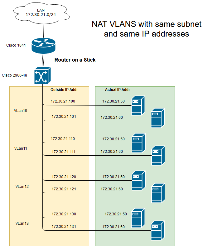
I purchased a Cisco router and L2 switch to configure as a router on a stick. In principle I want to setup VLans and NAT the outside IP addresses to the related inside device. From the outside, it would look like each individual device has a unique IP address. This is illustrated in the diagram. All my reading tells me that the router will object because the VLans would share the same sub-nets.

How can I achieve the requirement? Can I NAT the external IP addresses in the router table to the respective VLans? Is there a way of getting past the problem of VLans sharing a subnet?

Simplified Network Diagram

7
  • Maybe not. I have a 1841 router. The Cisco documentation says a 2500 series router is needed to run the IP nat outside source list. The 2500 was superseded by 2600 series, which went out of support 2008. I will try and see if the 1841 IOS includes the commands I need.
    – user643684
    Commented May 31, 2019 at 11:55
  • The 1800 series is much, much newer than the 2500 series, and it can run outside source NAT.
    – Ron Maupin
    Commented May 31, 2019 at 14:53
  • The problem you are going to have is with a single router you cannot have different interfaces (even the subinterfaces) addressed with the same or overlapping networks. You will need multiple routers.
    – Ron Maupin
    Commented May 31, 2019 at 14:54
  • OK. How many routers will I need? I will study the documentation over the next week or so and see if I can figure out how to make it work. My initial random thought is that I will need a 2nd router to NAT to an intermediate set of IPs (invisible to the outside) that are then NATed to the IP pairs.
    – user643684
    Commented May 31, 2019 at 20:46
  • Are you wedded to a cisco soloution or would you consider other platforms? I belive this can be done with a single Linux box running a modern kernel. Commented May 31, 2019 at 23:20

2 Answers 2

4

NAT happens on a device that can perform NAT, e.g. a router (even layer-3 switches cannot NAT, except for something like the 65xx series). The outside and inside addressing is placed on different interfaces of the NAT device. You will need to either put in a router on each VLAN between the router and hosts, or it may be that your hosts can themselves NAT between a physical and virtual interface, but that is off-topic here (you could try to ask about that on Server Fault).

The bigger problem is the VLAN addressing. Your router will need each interface (VLAN) to be in a different network. You cannot configure the router with the same or overlapping networks on different interfaces. Also, you are trying to use base 10 address separation of VLAN addresses in an inherently binary number (IP address), and that doesn't work well. That means that the shortest prefix for each VLAN with addressing like you have is /29, giving you eight (six usable) host addresses. A network of /28 would be 16 (14 usable) host addresses, which is longer than the separation of 10 that you have, leading to overlapping networks on your VLANs.

Using /31 addressing would work, and it can be configured on a Cisco router, but some host OSes, e.g. Windows, do not support it. It would look like this:

  • VLAN 10 is 172.30.21.100/31, which is 172.30.21.100 to 172.30.21.101
  • VLAN 11 is 172.30.21.110/31, which is 172.30.21.110 to 172.30.21.111
  • VLAN 12 is 172.30.21.120/31, which is 172.30.21.120 to 172.30.21.121
  • VLAN 13 is 172.30.21.130/31, which is 172.30.21.130 to 172.30.21.131

Using /30 addressing has some problems with your chosen VLAN addresses:

  • VLAN 10 is 172.30.21.100/30, which is 172.30.21.100 to 172.30.21.103, but 172.30.21.100 is the network address, unusable as a host address
  • VLAN 11 is 172.30.21.108/30, which is 172.30.21.108 to 172.30.21.111, but 172.30.21.111 is the broadcast address, unusable as a host address
  • VLAN 12 is 172.30.21.120/30, which is 172.30.21.120 to 172.30.21.123, but 172.30.21.120 is the network address, unusable as a host address
  • VLAN 13 is 172.30.21.128/30, which is 172.30.21.128 to 172.30.21.131, but 172.30.21.131 is the network address, unusable as a host address

Using /29 addressing has a couple of problems.

  • VLAN 10 is 172.30.21.100/29, which is 172.30.21.96 to 172.30.21.103
  • VLAN 11 is 172.30.21.104/29, which is 172.30.21.104 to 172.30.21.111, but 172.30.21.111 is the broadcast address, unusable as a host address
  • VLAN 12 is 172.30.21.120/29, which is 172.30.21.120 to 172.30.21.127, but 172.30.21.120 is the network address, unusable as a host address
  • VLAN 13 is 172.30.21.128/29, which is 172.30.21.128 to 172.30.21.135

If you can adjust the VLAN addressing on your router to something else, and your hosts can NAT internally, then you could do this without placing NAT devices on the VLANs, otherwise you need to NAT on each VLAN, requiring a NAT device for each VLAN.

1
  • Comments are not for extended discussion; this conversation has been moved to chat.
    – Ron Maupin
    Commented Jun 2, 2019 at 6:03
0

The Requirements This solution aims to solve the problem of connecting pairs of hosts. Each IP address of hosts of the pair is different. All pairs share the same two IP addresses. The IPs of the pairs are:

172.30.21.50

172.30.21.60

The Use Case here is for a test and development system. Only average network speed is required. There is one connection to the rest of the network. The solution must be efficient in space, energy usage and cost.

The Cisco "Solution" There are quite a few questions out there seeking solutions to a variety of problems with overlapping subnets. The more I learn, the less likely a pure and practical Cisco solution is achievable. The range of solutions offered by Cisco is very narrow.

A lot of the problems could be solved if the IP could be NATed at the switch ports. By definition L2 switches can't do that. L3 switches don't do that. That is the job of a router. If putting one Cisco router between 2 networks is a good idea, putting a Cisco router on every switch port to solve my problem is not.

The solution I propose is to implement switch port routers with Raspberry Pi's fitted with 2 USB to LAN adapters. They would be configured as routers with NAT enabled. One RasPi connected to 1 switch port can then route to a pair of servers.For my application (SSH and file transfers), a high performance network is not required, and Raspi's with USB/LAN adapters won't provide it. A Raspberry Pi uses less space, less power and costs less than a Cisco router. The concept is illustrated in the diagram. NATing the IP traffic with the routers should make the VLANs easy to setup.

If performance is required, then proper routers would be used, plus a rack to install them into. The Cisco 1841 router only has two ports, so I would need a router on each switch port. Double the number of Raspi's would be required.

The whole point of VLANs is to be able to create a virtual network in software. Having to double NAT IPs in hardware to work around programmed software constraints of the switch is not good.

I concluded that a Cisco based solution was too complex and required too many devices. It is a bad solution.
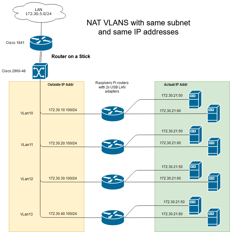
Network with overlapping subnets

I decided that a layer based solution was the wrong approach. I started looking at an IP pipeline illustrated in the diagram below. The first router NATs the externally visible address pairs to another subnet specifically to separate the VLAN subnet ranges so they are acceptable to the switch. The VLAN then directs traffic to specific switch ports. The router then NATs the intermediate address to the actual address of the server.
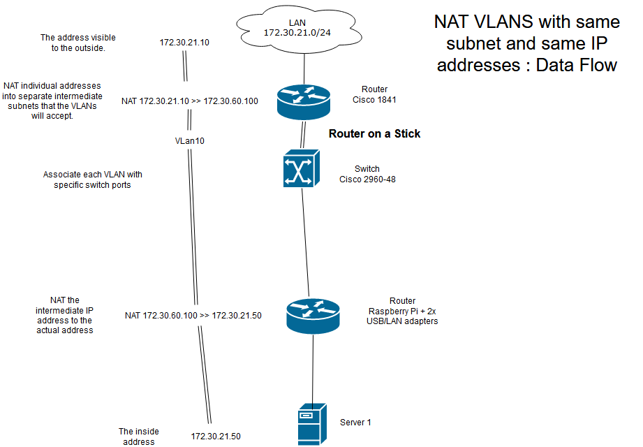
IP Pipeline Illustration

The IPTables Solution

Having decided that a Cisco based solution won't meet the design requirements, I looked for alternatives. It didn't take long to find IP Tables. IPTables (almost) ignores layers. It is specifically designed to process IP pipelines.

The solution I came up with is as follows:

My network has a Linux IPtables based firewall/router.

This will be connected to a PC with a lot of PCI slots. MoBos made for bit coin mining are ideal candidates. Quad Gb NICs are now readily available. I will call this the switch host. It is relatively cheap and easy assemble a PC with 24 Gb LAN ports. A lot cheaper than a new Cisco device.

The IPtables process pipeline is illustrated below.

Step 1. Write a IPtables rule on the firewall that sends a block of IP addresses to a specific port on the switch host. 172.30.21.50 to 99 > 172.30.21.100 The block is the IP addresses that map to the IP pairs. The port 172.30.21.100 is connected to the switch host with many network cards (quad PCI 1Gb NICs) installed .

Step 2. The IPtable rules on the switch host direct each IP address of the block to a specific LAN port. Those same rules NAT the address to match one of the IP pairs

172.30.21.50 > NAT 172.30.21.50 > eth1

172.30.21.51 > NAT 172.30.21.60 > eth0

172.30.21.52 > NAT 172.30.21.50 > eth2

172.30.21.53 > NAT 172.30.21.60 > eth3

THE APPLIED SOLUTION After going through a series of iterations, starting with a Cisco based approach, I ended up with the solution outlined below.

Rather than use IPTables, I used nft, its modern replacement, running on a single Linux box. The rules here don't allow scripts to be posted so I will describe what was done. There are several parts to the solution shown in the diagram. nft design
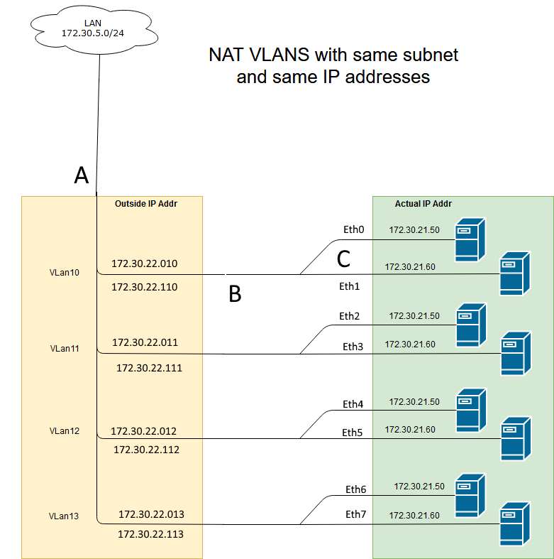
PART A I set up a filter so that only traffic within the IP range of the connected devices was allowed in.

PART B nft is setup to direct specific IP addresses to specific ports. They act like VLANS but they are not, because all the IP addresses are in the same domain. The packets are DNATed to route them correctly. An packet from the network is sent to the correct port and the destination IP is changed to match the host.

PART C Part C needs to differentiate between traffic to the neighbour of a pair of hosts, or out to the rest of the network.

Note there is no requirement for comms across different pairs of host. There is only a requirement for comms between the two hosts that make up a pair. The setup below will allow for comms between pairs of hosts.

nft is setup so that any traffic with a destination IP of it's neighbour is steered to the correct eth port and vice versa. For example, if a packet from host 172.30.21.50 (source) comes in from eth0, and has a destination IP of 172.30.21.60 (its neighbour), then nft sends it out through port eth1. No NATing is required.

If a packet comes in from the network with a destination IP of 172.30.22.010, then it is DNATed to 172.30.21.50 with the source untouched (ip xxx.xxx.xxx.xxx) and sent out eth0 port.

The reply to that packet coming back in eth0 port with have a dest IP of xxx.xxx.xxx.xxx, and a source of 172.30.21.50. This is SNATed to 172.30.22.010 and sent out to the network. The network thinks it is communicating with a host on IP 172.30.22.010.

Part C differentiates between external traffic and traffic between pairs. From outside, each host looks like it has its own IP address. Each host can communicate with its neighbour without knowing that there are multiple pairs of hosts with the same IP addresses. All of this is done with a single Linux box with one ethernet port per host.

Bitcoin Switch This solution is limited by the number of available ports on the Linux box. The work around is to use machine designed for bit coin mining. These have many more pci-express connectors than a standard MoBo. Each connector can take a 4-way network card. It isn't hard to find a mobo with more than 15 pci-e interfaces. That makes a single Linux box with 60 or more ports a practical solution.

The throughput of a single Linux box based on a bit coin MoBo will not match a purpose build Cisco switch/router but it works for a lab test environment (my application). It is a low cost and efficient solution in terms of:

  • energy consumption,
  • space,
  • single box solution,
  • $$ cost.

It is a much better solution than Cisco can provide.

10
  • "I think there is a good chance this could be done with a single Linux box and IP Tables." That would be off-topic here. You could try to ask about that on Server Fault for a business network.
    – Ron Maupin
    Commented Jun 2, 2019 at 2:49
  • "Having to double NAT IPs in hardware to work around programmed software constraints of the switch is not good." A switch is a layer-2 device, and it knows nothing about layer-3 (IP) addresses. I do not think you quite grasp the network layer separation. Most switching is done completely in hardware, not software. The original bridges used software, but it was slow. Switching uses hardware, and can now switch (bridge) at wire speed. NAT is resource intensive, and it can greatly slow traffic. Cisco has decided that it will only NAT with a hardware assist, and that is only done on routers.
    – Ron Maupin
    Commented Jun 2, 2019 at 2:50
  • I think that a single (Linux-based) device could be used; however, I doubt that the required software for doing this already exists. It would be possible to write a software that interfaces with the operating system on OSI layer-2 (raw ethernet frames that contain IP packets). Maybe you would even have to modify the Linux kernel. However, writing such a software would be a lot of effort. I would prefer a "standard solution" (such as 10 Raspberry devices with existing software). Commented Jun 2, 2019 at 6:57
  • My current thinking is to forget the OSI model and focus on a pipeline solution. All I need is something that will NAT and steer IP data flow. I am starting to read up on IPtables. My initial assessment is that it can do exactly what I want. I have been running Linux/IPtables based firewalls for years via a GUI. The current version is running on a fanless mini PC at full fibre broadband speed. I have no need for high speed and no concerns about speed with Linux/IPtables running on a bit coin MoBo. The Raspi solution would also require IPtables.
    – user643684
    Commented Jun 2, 2019 at 11:38
  • IPTables and other host/server configurations are off-topic here. You can ask about that on Server Fault for a business network. The manufacturer of a device must offer optional, paid support for the device to be on-topic here, but you do not have that for your Linux boxes.
    – Ron Maupin
    Commented Jun 4, 2019 at 13:23

Your Answer

By clicking “Post Your Answer”, you agree to our terms of service and acknowledge you have read our privacy policy.

Not the answer you're looking for? Browse other questions tagged or ask your own question.