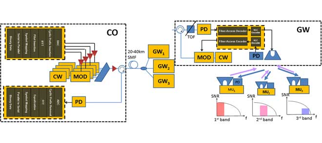
I was trying to understand one the research paper form IEEE, on Bidirectional Visible Light Communication, but I am unable to understand one of its Block diagram.
I am sharing his block diagram, please some one help me to understand it .
I was trying to understand one the research paper form IEEE, on Bidirectional Visible Light Communication, but I am unable to understand one of its Block diagram.
I am sharing his block diagram, please some one help me to understand it .
 "Proposed bidirectional network architecture combining the [visible light communication] VLC access network and the [time-wavelength-division-multiplexed passive optical network] TWDM-PON. Central office (CO); gateway (GW); mobile unit (MU); modulator (MOD), photodiode (PD)."
( bigger image )
(From the abstract of the paper by Chi-Wai Chow et. al. "Network Architecture of Bidirectional Visible Light Communication and Passive Optical Network" at http://dx.doi.org/10.1109/JPHOT.2016.2566340 ).
In this diagram, packets of data flow in two directions:
As usual, the arrows indicate the direction of information flow.
The diagram on the left half shows a standard wavelength-division multiplexing communication system that bidirectionally sends data between a central office (CO) to several gateways (GW) over many kilometers of single-mode fiber (SMF).
details:
Packets of data (in the form of electrical impulses) flow in one direction along the copper wire going into each Electro-absorption modulator or electro-optic modulators, each one modulating the light of a different-colored laser.
Logically the same data (in the form of pulses of light) flows in one direction from the modulator to the multiplexer, and from the multiplexer to the optical circulator.
The optical circulator at the central office guides those locally-generated photons out to the kilometers of fiber to the gateways.
Meanwhile the same optical circulator at the central office guides incoming packets of data from the gateways to the photodiode (PD).
Packets of data flow in both directions through the same single-mode fiber, which is 20 kilometers to 40 kilometers long.
The photodiode at the central office converts data from the remote gateways (still in the form of pulses of light) to an electrical signal for further decoding.
(The two yellow boxes containing white text on gray background give more details showing that the central office encodes the data digitally using orthogonal frequency-division multiplexing (OFDM) before sending it to a modulator, and the data received from the remote gateways is also decoded using OFDM).
The diagram on the right half gives more details about a typical one of the gateways from the left half of the diagram, and also how that one gateway communicates bidirectionally with multiple mobile units.
details:
I'm mystified by the TOF box. From the context I'm guessing it's a frequency-selective optical bandpass filter tuned to the color of one particular laser at the central office, so this particular gateway can ignore the messages from all the other lasers at the central office and all the other lasers at other gateways, messages that (simultaneously) go though the same optical fiber. What does TOF mean?
Packets of data (in the form of pulses of laser light) from the central office come into the optical circulator of the gateway, which guides them into the photodiode (PD). The packet of data from the photodiode (now in the form of pulses of electrical energy) are decoded, then re-encoded into some visible light communication (VLC) protocol. The packet of data is sent to a (ceiling light?) LED that shines down on a bunch of mobile units (illustrated by the blue arrows). Each mobile unit has its own photodiode that receives packets of data from the gateway.
Packets of data generated by a mobile unit (MU) are sent to the the LED on the mobile unit, which converts them to pulses of visible light, represented by the purple arrows. That light shines up on the photodiode (PD) of the gateway. The gateway decodes that visible light into electrical pulses, then uses a single electro-optic modulator to convert the packet of data from the mobile unit into the form of pulses of light from the continuous-wave laser (CW). Data only travels one direction along the fiber from the gateway's modulator to the gateway's optical-circulator. The optical circulator at the gateway routes the data from the mobile units out the optical fiber towards the central office.
EDIT:
The two main (only?) ways to send data are:
With currently available technology, the lowest-cost way to transmit "low-speed" data through free space or through fiber optics is direct modulation -- simply turn the electrical power going into the LED or laser on and off. (I hear that transmitting 3 Mbit/s by turning on and off a red LED, as with TOSLINK, is relatively easy). Laser diodes can be turned on and off a little faster than LEDs.
With currently available technology, the lowest-cost (?) way to transmit "high-speed" data through fiber optics at more than a gigabit/s -- faster than a LED or a laser can be turned on and off -- is to generate a constant beam of photons with a CW laser, then modulate how much of that beam gets through using some kind of optical modulator.