2

In the previous question I have been trying to optimize switching topology.

Now I would like to implement redundancy. And here are the problems I faced.

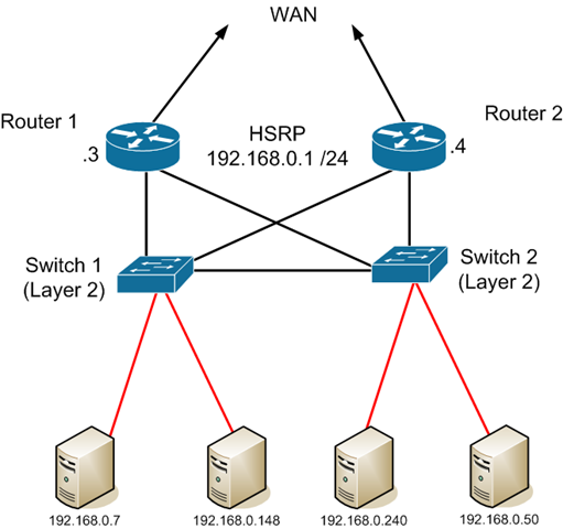
Assuming the following topology

Topology

As routers we use Mikrotik. Switches are cisco.

Redundancy between two routers will be achieved through VRRP. Unfortunately I can't understand how I can establish NAT after.

We have /28 public address range. It is obvious that both Mikrotiks have to have the IPs from our public range to use the CPE as gateway. VRRP will be inside the network (private). This part is easy and clear.

But then, how to make NAT. While on both Mikrotiks I have to mirror the configuration, thus both will have the same IP addresses in the public range (I had to configure all the list of IPs in order to implement dst-nat).

And from here I can't imagine how should I implement this.

I was thinking about making VRRP inside our public range. But can't yet make a proper picture of the implementation. Or do I need to create two VRRPs, inside and outside the network?

How does usually configuration of a such network topology looks?

3 Answers 3

1

NAT is a problem with dual routers because the tables in NAT don't get shared between the routers.

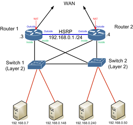
That topology will break NAT if the traffic is asymmetric. Asymmetric traffic will come from the WAN to the wrong router and get passed to the correct router on an inside interface instead of the outside interface, so it will never translate.

EDIT:

This is your drawing modified for what I mean. The link between the routers must be the best path from one router to the other.

enter image description here

5
  • What do usually people do in such a case? I just do not want to rely on one Mikrotik, we've got a second one. Does it actually mean that the best solution will be to introduce a second Mikrotik as "sleeping" backup where we can only physically re-connect? Or to have a third, more reliable device, that will do the job?
    – Dex
    Commented Sep 11, 2015 at 16:32
  • You can make sure that any packets coming in from the WAN come into the router on an interface marked as outside. This may involve a routed link between the WAN routers that is the best path from one to the other and is marked as outside on each router. The WAN routers should not NAT on this link. This may create other problems for your design, so you should test thoroughly.
    – Ron Maupin
    Commented Sep 11, 2015 at 23:09
  • And what if one of the routers is "active backup", no traffic will go through it, unless the main one is down?
    – Dex
    Commented Sep 12, 2015 at 10:25
  • No, they will both be active. You want to make sure that when traffic destined for one router's WAN interface comes into the other router it will be sent to the correct router and come into it on an outside, not inside, interface.
    – Ron Maupin
    Commented Sep 12, 2015 at 19:19
  • Okay, I just satisfactorily implemented Router's VRRP. Unfortunately for the moment I do not see how should I implement switch backup, while I removed one from the schema. In the end everything work good in Mikrotik.
    – Dex
    Commented Sep 12, 2015 at 20:41
1

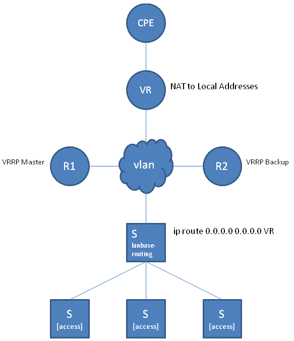
In order to achieve requirements with minimum costs (working with existing cisco 2960s, two Mikrotik routers and one CPE from ISP, where this CPE is covered with SLA) and avoid using single Mikrotik (I trust a bit more to cisco switch than to Mikrotik) I made following:

  1. Changed the teamplate of cisco switch to lanbase-routing
  2. Created vlan and placed it in the public IP-address range
  3. Created VRRP on both Mikrotiks (they are also using public IP addresses)
  4. Routed all traffic from Mikrotiks to CPE, but through VRRP interface
  5. Created all needed IP addresses on the VRRP interface
  6. Now, routing from the network is made by cisco, nat by mikrotiks

Here is the simple schema, I've created to illustrate everything (R1, R2 and VR are in VRRP). R1 has 254 priority and R2 is 1, plus preemption-mode enabled (to always use R1 as Master if it is available, I like it more)

enter image description here

Fortunately it works, now the second part left, start using two switches. How should I implement this I do not know yet.

All additional IP addresses, that I had to assign to the VRRP work perfectly. Master router puts them up, backup does nothing, for it the VRRP is sort of down.

1
  • 1
    I updated my answer with a drawing.
    – Ron Maupin
    Commented Sep 12, 2015 at 23:30
1

if you want to use HSRP/GLDP , you should use 2 Cisco routers (881, 1841+Hwic 4x100m , 1941+Hwic 4xESG 1G for gigabit) and replace the mikrotik.Then the life it more simple, configure virtual Getaway interface (ex.192.168.0.1 on R1 and R2) then setup Hsrp interfaces (ex. fe0/3) on R1 (Active) ( 192.168.0.2) , on R2 standby (fe0/3) (192.168.0.3). NAT configuration inside should be used on virtual Getaway (192.168.0.1), NAT outside on each WAN interface of R1 and R2. you can allso create a DHCP server for virtual getaway 192.168.0.1

Your Answer

By clicking “Post Your Answer”, you agree to our terms of service and acknowledge you have read our privacy policy.

Not the answer you're looking for? Browse other questions tagged or ask your own question.