3

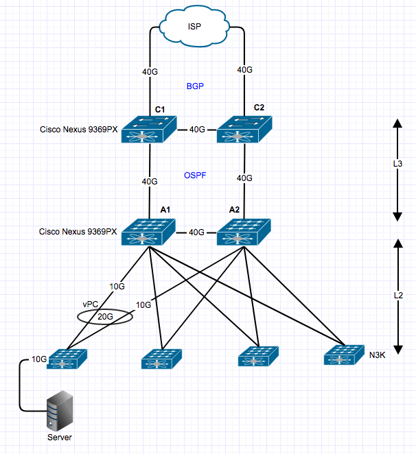
This is going to be new network in my datacenter and i have question related vPC, as you can see i have A1/A2 switch (L3/L2 routing) in aggregation layer and C1/C2 switches for Core (L3 routing). I am planning to implement vPC between TOR and Aggregation layer to avoid STP and utilize full bandwidth.

Question: If TOP switch send traffic to Aggr layer switch and it will send traffic to both link using hash algorithm in that case how A2 switch will send traffic to upstream core switch (L3)? Does A2 switch send traffic to A1 using trunk or it will send traffic directly to C2 switch and then C2 switch forward to C1 (because C1 is primary BGP switch)

I am new in vPC so trying to understand how switch will handle upstream traffic.

enter image description here

EDIT:

Question:

  • Should i create vPC between Core C1/2 and Aggr A1/A2 to resolve this routing loop?
6
  • 4
    Since the A1-C1 and A2-C2 links are routed, isn't it just a matter of the routing table? When both links have equal metrics the data should flow directly to the respective core router.
    – Zac67
    Commented Feb 20, 2018 at 20:14
  • So are you trying to introduce enhanced vPC between Aggregation and Core? Commented Feb 20, 2018 at 20:26
  • @Datagram.Network I didn't thought about that do you think it would be a good idea to put vPC between core and aggr layer?
    – Satish
    Commented Feb 20, 2018 at 20:44
  • 2
    Please check out cisco documentation as there is many caveats. cisco.com/c/en/us/products/collateral/switches/… Commented Feb 20, 2018 at 21:07
  • I believe if i create vPC (LACP) between L3 and L2 in that case my routing will be straight forward right?
    – Satish
    Commented Feb 21, 2018 at 15:59

2 Answers 2

4

It depends on whether you have a vPC between the aggregation and core layers.

If the connection between (A1, A2) and (C1, C2) is a vPC, then the switch always prefers "local forwarding". That is, any packet that is received on A1 will be sent to C1, and any packet that is received on A2 will be send to C2. The idea is to have the packet pass through only one ASIC in the data path; if a packet that was received on A2 were sent to C1 via A1, then it would have to pass through two ASICs thereby increasing latency. It would also consume bandwidth on the A1-A2 link.

If the connection between (A1, A2) and (C1, C2) is a normal OSPF topology, i.e. does not use vPC, then the packet will follow usual L3 forwarding rules. If the packet was received on A2 but the route lookup yields C1 as the next hop, then the packet will go to A1 and from there to C1.

The interesting case here is a load-balanced route, with both C1 and C2 as possible next-hops. In this case you will have to ask Cisco what will happen because this is dictated by internal ASIC behaviour: i.e. will A2 always "prefer" the directly connected hop (i.e. C2), or will the normal L3 hashing logic anyway kick in, and send packets to both C1 (via A1) and C2 (directly) based on the flow.

1
  • In core C1 & C2 L3 switches C2 is BGP secondary switch in that case C2 will forward traffic to C1 because C1 is primary in BGP and C2 is redundant link
    – Satish
    Commented Feb 21, 2018 at 5:09
1

Okay. Let me paraphrase your question. You are asking the traffic flow from ToR to the core switches. If I understand your question right, then it all depends on your routing table entries on A2.

Let's say traffic wants to reach the core. Then the packet will be switched to either of the A switches where the default gateway is present assuming that you have a FHRP protocol running. From there, it will have to look at the routing table to decide the routing path. Now packet in A2 will be routed according to the way the route is learnt. If it is learned via A1's SVI then it will take that route (provided a separate link is provisioned) . If the route is learnt via C2, then the packet will be routed to C2.

From the design point, why are you using 40G between the aggregation switches? let me know if you have further questions.

14
  • Using 40G between aggr switches to Create vPC between two switch and i have L2 network between Aggr and access layer. This topology look like spine-leaf but its really not true spine-leaf
    – Satish
    Commented Feb 21, 2018 at 15:57
  • you don't have to use a 40G between the aggregation switches for peer link. You can reduce the capacity to say 20G. hope it helps.
    – Bub
    Commented Feb 21, 2018 at 17:42
  • i have lots of 40G ports available so i used that one :)
    – Satish
    Commented Feb 21, 2018 at 19:09
  • Okay. Then it is alright.
    – Bub
    Commented Feb 22, 2018 at 6:58
  • Have you got the answer for your question?
    – Bub
    Commented Feb 22, 2018 at 11:52

Your Answer

By clicking “Post Your Answer”, you agree to our terms of service and acknowledge you have read our privacy policy.

Not the answer you're looking for? Browse other questions tagged or ask your own question.