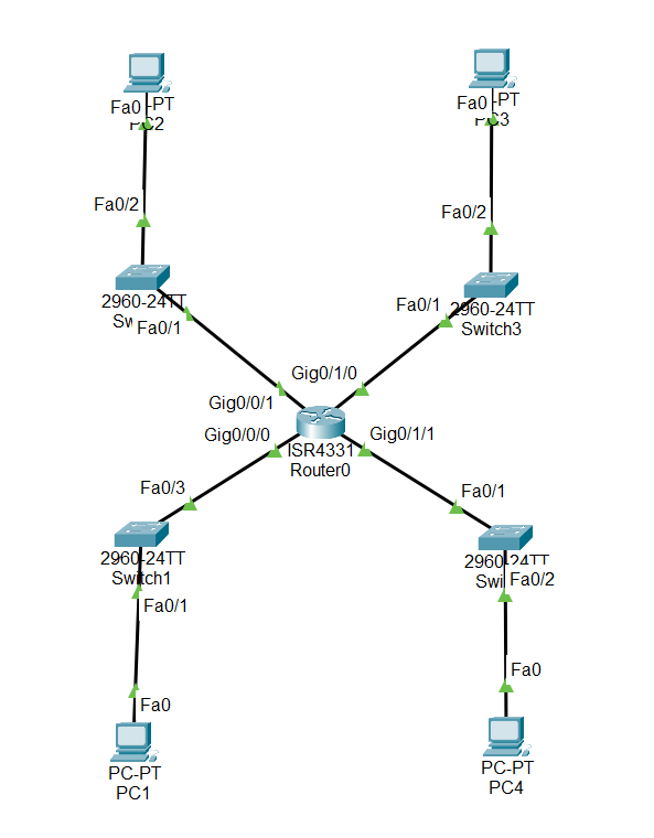
i'm working on this topology for so long and i didn't manage to make every network speak together with different VLAN on each network. On this topology:
When i trace a packet sent from PC3 to PC4, the packet reaches the Router, the Router drops the packet with this message: "Router does not have the VLAN indicated on the IEEE 802.1q frame tag. It drops the frame."
I want PC1(10.1.1.1) to ping PC2(10.1.2.1),PC3(10.1.3.1),PC4(10.1.4.1) and PC2 to ping PC1,PC3,PC4 and etc.. with respect that each of these PC's has different VLAN. I already made the VLANs as you will see on each Switch Configuration.
Here's the Router Configuration:
hostname Router
!
ip cef
no ipv6 cef
!
spanning-tree mode pvst
!
interface GigabitEthernet0/0/0
no ip address
!
interface GigabitEthernet0/0/1
no ip address
duplex auto
speed auto
!
interface GigabitEthernet0/0/2
no ip address
duplex auto
speed auto
shutdown
!
interface GigabitEthernet0/1/0
switchport mode trunk
switchport nonegotiate
!
interface GigabitEthernet0/1/1
switchport mode trunk
switchport nonegotiate
!
interface GigabitEthernet0/1/2
switchport mode access
switchport nonegotiate
!
interface GigabitEthernet0/1/3
switchport mode access
switchport nonegotiate
!
interface Vlan1
ip address 10.1.0.254 255.255.255.0
!
router rip
!
ip classless
!
ip flow-export version 9
!
line con 0
!
line aux 0
!
line vty 0 4
login
!
end
Here's the Switch1 Configuration:
hostname Switch1
!
spanning-tree mode pvst
spanning-tree extend system-id
!
interface FastEthernet0/1
switchport access vlan 10
switchport mode access
!
interface FastEthernet0/2
!
interface FastEthernet0/3
switchport mode trunk
!
..
..
!
interface Vlan1
ip address 10.1.1.254 255.255.255.0
!
line con 0
!
line vty 0 4
login
!
line vty 5 15
login
!
end
!
Here's the Switch2 Configuration:
hostname Switch2
!
spanning-tree mode pvst
spanning-tree extend system-id
!
interface FastEthernet0/1
switchport mode trunk
!
interface FastEthernet0/2
switchport access vlan 20
switchport mode access
!
..
..
!
interface Vlan1
ip address 10.1.2.254 255.255.255.0
!
line con 0
!
line vty 0 4
login
!
line vty 5 15
login
!
end
!
Here's the Switch3 Configuration:
hostname Switch3
!
spanning-tree mode pvst
spanning-tree extend system-id
!
interface FastEthernet0/1
switchport mode trunk
!
interface FastEthernet0/2
switchport access vlan 30
switchport mode access
!
..
..
!
interface Vlan1
ip address 10.1.3.254 255.255.255.0
!
line con 0
!
line vty 0 4
login
!
line vty 5 15
login
!
end
!
Here's the Switch4 Configuration:
hostname Switch4
!
spanning-tree mode pvst
spanning-tree extend system-id
!
interface FastEthernet0/1
switchport mode trunk
!
interface FastEthernet0/2
switchport access vlan 40
switchport mode access
!
..
..
!
interface Vlan1
ip address 10.1.4.254 255.255.255.0
!
line con 0
!
line vty 0 4
login
!
line vty 5 15
login
!
end
!

