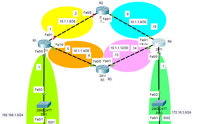
In this topology I have configured the devices in this way:
R1:
Building configuration...

Current configuration : 916 bytes
!
version 15.1
no service timestamps log datetime msec
no service timestamps debug datetime msec
no service password-encryption
!
hostname R1
!
!
!
!
!
!
!
!
no ip cef
no ipv6 cef
!
!
!
!
license udi pid CISCO2811/K9 sn FTX1017U862-
!
!
!
!
!
!
!
!
!
!
!
spanning-tree mode pvst
!
!
!
!
!
!
interface FastEthernet0/0
 ip address 192.168.1.1 255.255.255.0
 duplex auto
 speed auto
!
interface FastEthernet0/1
 ip address 10.1.1.1 255.255.255.252
 duplex auto
 speed auto
 shutdown
!
interface FastEthernet1/0
 ip address 10.1.1.5 255.255.255.252
 duplex auto
 speed auto
!
interface FastEthernet1/1
 no ip address
 duplex auto
 speed auto
 shutdown
!
interface Vlan1
 no ip address
 shutdown
!
ip classless
ip route 172.16.3.0 255.255.255.0 10.1.1.2
ip route 172.16.3.0 255.255.255.0 10.1.1.6 5
!
ip flow-export version 9
!
!
!
!
!
!
!
!
line con 0
 logging synchronous
!
line aux 0
!
line vty 0 4
 login
!
!
!
end
R2:
Building configuration...

Current configuration : 714 bytes
!
version 15.1
no service timestamps log datetime msec
no service timestamps debug datetime msec
no service password-encryption
!
hostname R2
!
!
!
!
!
!
!
!
ip cef
no ipv6 cef
!
!
!
!
license udi pid CISCO2811/K9 sn FTX101723IN-
!
!
!
!
!
!
!
!
!
!
!
spanning-tree mode pvst
!
!
!
!
!
!
interface FastEthernet0/0
 ip address 10.1.1.2 255.255.255.252
 duplex auto
 speed auto
!
interface FastEthernet0/1
 ip address 10.1.1.9 255.255.255.252
 duplex auto
 speed auto
!
interface Vlan1
 no ip address
 shutdown
!
ip classless
ip route 172.16.3.0 255.255.255.0 10.1.1.10
ip route 192.168.1.0 255.255.255.0 10.1.1.1
!
ip flow-export version 9
!
!
!
!
!
!
!
!
line con 0
!
line aux 0
!
line vty 0 4
 login
!
!
!
end
R3:
Building configuration...

Current configuration : 715 bytes
!
version 15.1
no service timestamps log datetime msec
no service timestamps debug datetime msec
no service password-encryption
!
hostname R3
!
!
!
!
!
!
!
!
ip cef
no ipv6 cef
!
!
!
!
license udi pid CISCO2811/K9 sn FTX1017BW6O-
!
!
!
!
!
!
!
!
!
!
!
spanning-tree mode pvst
!
!
!
!
!
!
interface FastEthernet0/0
 ip address 10.1.1.6 255.255.255.252
 duplex auto
 speed auto
!
interface FastEthernet0/1
 ip address 10.1.1.13 255.255.255.252
 duplex auto
 speed auto
!
interface Vlan1
 no ip address
 shutdown
!
ip classless
ip route 172.16.3.0 255.255.255.0 10.1.1.14
ip route 192.168.1.0 255.255.255.0 10.1.1.5
!
ip flow-export version 9
!
!
!
!
!
!
!
!
line con 0
!
line aux 0
!
line vty 0 4
 login
!
!
!
end
R4:
Building configuration...

Current configuration : 889 bytes
!
version 15.1
no service timestamps log datetime msec
no service timestamps debug datetime msec
no service password-encryption
!
hostname R4
!
!
!
!
!
!
!
!
no ip cef
no ipv6 cef
!
!
!
!
license udi pid CISCO2811/K9 sn FTX1017OPU6-
!
!
!
!
!
!
!
!
!
!
!
spanning-tree mode pvst
!
!
!
!
!
!
interface FastEthernet0/0
 ip address 172.16.3.1 255.255.255.0
 duplex auto
 speed auto
!
interface FastEthernet0/1
 ip address 10.1.1.10 255.255.255.252
 duplex auto
 speed auto
!
interface FastEthernet1/0
 ip address 10.1.1.14 255.255.255.252
 duplex auto
 speed auto
!
interface FastEthernet1/1
 no ip address
 duplex auto
 speed auto
 shutdown
!
interface Vlan1
 no ip address
 shutdown
!
ip classless
ip route 192.168.1.0 255.255.255.0 10.1.1.9
ip route 192.168.1.0 255.255.255.0 10.1.1.13 5
!
ip flow-export version 9
!
!
!
!
!
!
!
!
line con 0
!
line aux 0
!
line vty 0 4
 login
!
!
!
end
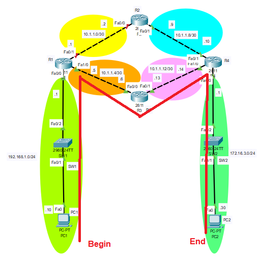
When I ping from PC1 to PC2, the path to go from PC1 to PC2 is as follows:
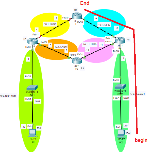
But the way back, to go from PC2 to PC1 is as follows: (causing the packet to be discarded)
Question:
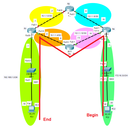
How can I make the return route, that is, from PC2 to PC1, be as follows, that is, although the path through the upper static route is active, it goes through the lower floating static route?
The packet tracer file is the following: https://www.mediafire.com/file/3dvgy683vestflg/Static_Routes.pkt/file


show running-configcommand, copy the text, paste it into the question, and use the Pre-formatted-Text feature ({}) that is right next to the image feature you used.